Once the 3D model is complete we are ready to start creating our 2D drawings based on these models. Again the reference based model is used so that any changes we make in our model, will automatically update in our 2D drawings.
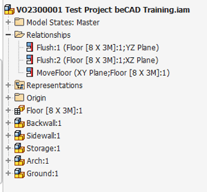
Before we start please double check that aside from the floor object, ALL other parts are inside a subassembly.
Use the AutoDrawing tool to start creating the drawings. As you will notice, most of it will run automatically.
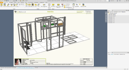
The first page will be an overview of our design with a structure list of all the subassemblies.
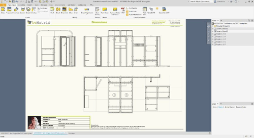
The second page is an overview page with a front, side and top view of our design.
You can use this page to place all the dimensions that you need for your panels or textiles.
You can also generate sections or cut- out views on this page or drag it to a new sheet to have it linked to eachother.
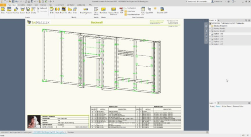
The remaining pages are for each subassembly within the project.
The Autodrawing tool will generate a view based on the subassemblies we created earlier, place and sort a parts list for that section and finally highlight all the connectors and smaller parts in a green overlay making them more visible.
You can use these pages to place balloons identifying the frames and parts with their corresponding item number of the partslist.
You can also place detailed views of parts to have a more detailed view of the connection.
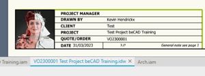
If you study the title section on every page, you’ll notice certain field are already filled in with the information we’ve provided at the start of our project.
- Your name based on the name provided in the application options
- Your clients name based on the client folder we selected at the start of the project
- The Project name and number by the information given at the start of the project
When everything is finished, use the export to PDF function to generate a pdf drawing. The drawing will be placed by default in the same location as that Inventor drawing file.